A 30 db 5w rf attenuator dc 18ghz with n type coaxial connectors 100 watt power attenuator an attenuator is an electronic device that reduces the power of a signal without appreciably distorting its waveform.
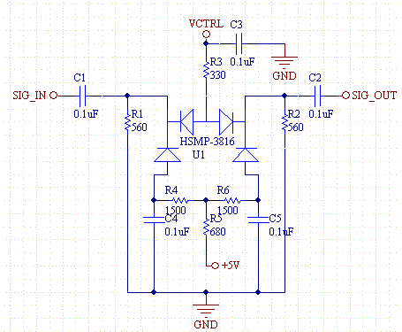
Variable rf attenuator circuit.
Attenuator circuit is both linear and reciprocal based on the application the attenuator can be unidirectional or bidirectional.
There are five common attenuator topologies used in microwave circuits the tee the pi the bridged tee the reflection attenuator and the balanced attenuator.
Over 400 coaxial surface mount and mmic attenuator models for 50 ohm 75 ohm system including fixed attenuators high power attenuators digital step programmable attenuators voltage variable attenuators and more.
It is this factor which makes the pin diode so useful in attenuator circuits.
One of the simplest forms of variable attenuators is the simple shunt diode type seen below.
Pin diode attenuators are a subset of variable rf attenuators and are useful for circuits requiring continuously changing attenuation levels.
Pin diodes have advantages over resistive networks and are the ideal rf component for these types of attenuators.
Dc passing and dc blocking models.
An increase in bias current will result in a decrease in rf resistance.
Subscribe to receive mini circuits news.
When the attenuator circuit is made symmetrical there will be no difference between the input port and the output port.
In figure 4 we can see how the pin diode acts as a current controlled rf resistor.
The tee pi and bridged tee each require two different resistor values while the reflection and balanced attenuators need only a matched pair of resistors.
In any rf system there is a need for a constant impedance and this design provides an acceptable match to 50ω over a wide range of attenuation levels.
Variable attenuator circuit.
Or better what you could do is building a variable attenuator through something like this see link where for every wheel with pins upper and lower you have to connect both r l signal and ground wires.
Variable rf attenuators are normally used in applications where it is necessary to continuously vary the level of a signal.
Typically variable attenuators provide a continuous level change by varying an analogue voltage on the input control line.
Rf attenuators over 400 coaxial surface mount and mmic attenuator models for 50 ohm 75 ohm syetem including fixed attenuators high power attenuators digital step programmable attenuators voltage variable attenuators and more.


